File:Groyne stencil.png
From FVCOM Wiki
(Difference between revisions)
Gcowles (Talk | contribs)
(Sketch of the separation of the control element at dikes or groynes. The shaded regions indicate the tracer control elements (TCEs).)
(Sketch of the separation of the control element at dikes or groynes. The shaded regions indicate the tracer control elements (TCEs).)
Latest revision as of 17:39, 9 January 2012
Sketch of the separation of the control element at dikes or groynes. The shaded regions indicate the tracer control elements (TCEs).
File history
Click on a date/time to view the file as it appeared at that time.
| Date/Time | Thumbnail | Dimensions | User | Comment | |
|---|---|---|---|---|---|
| current | 17:39, 9 January 2012 | 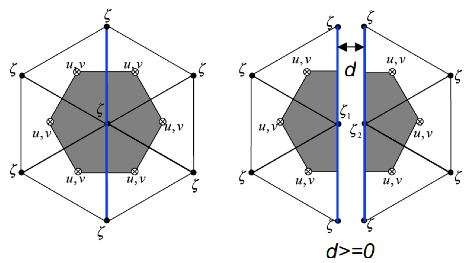 | 965×538 (102 KB) | Gcowles (Talk | contribs) | (Sketch of the separation of the control element at dikes or groynes. The shaded regions indicate the tracer control elements (TCEs).) |
- Edit this file using an external application (See the setup instructions for more information)
File links
The following page links to this file: